Digilab One Documentation
This is the getting-started guide for the Parleii Digilab One.
Before proceeding, please read Installing CH340 Driver to ensure your computer is properly set up to use Digilab One.
Hardware Diagram
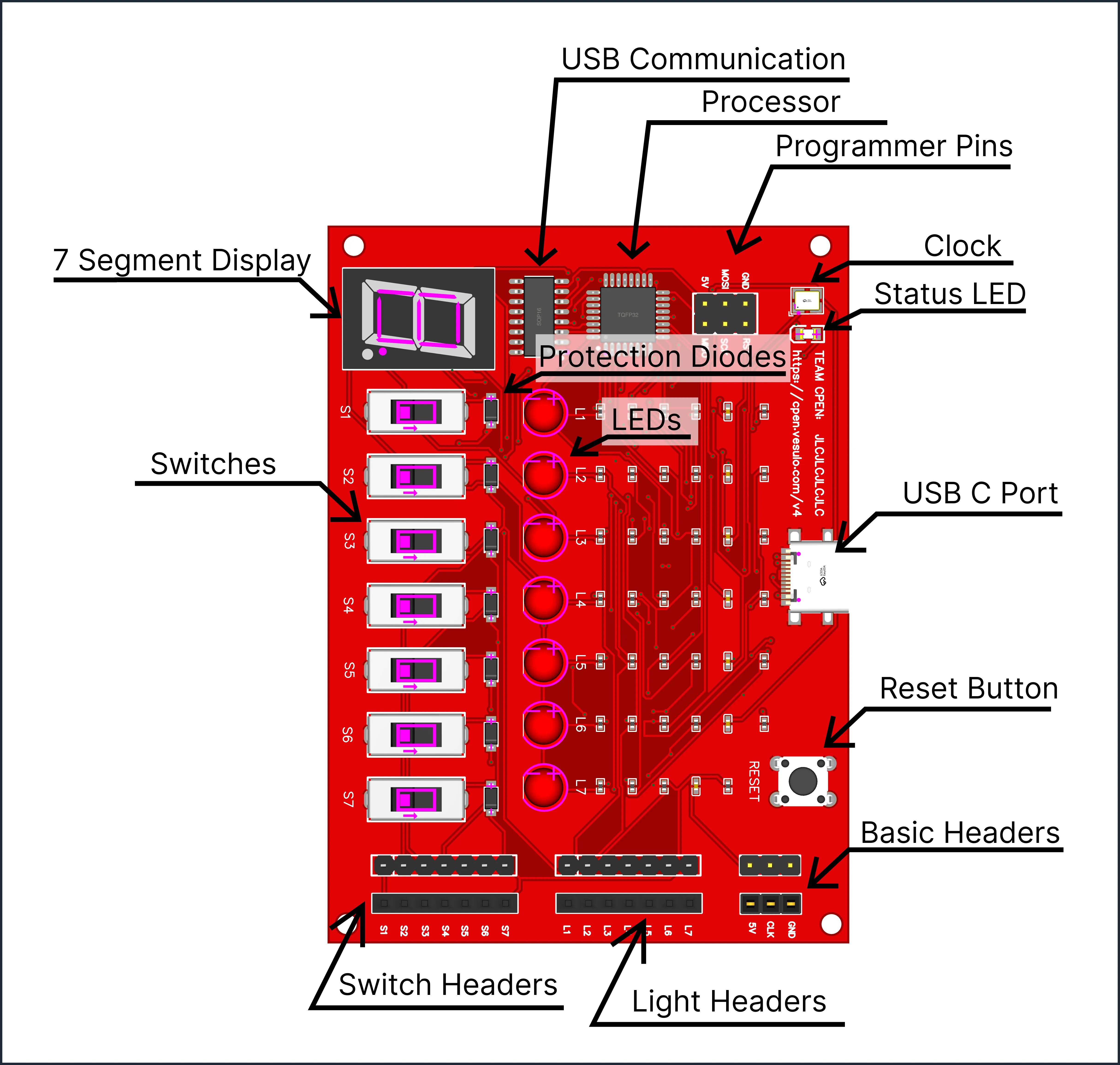
As shown in the diagram, the Digilab One includes the following components:
- Microcontroller: ATMEGA328P
- USB to Serial Converter: CH340
- Input Headers (Lights): 7 Male and 7 Female
- Output Headers (Switches): 7 Male and 7 Female
- Adjustable Clock
- 5V Power
- Ground Rail
Getting Started
The hardware is easy to set up. Simply connect a USB-C cable to the device and plug the other end into your computer. The device will be recognized as a serial port. Ensure that the CH340 Driver is installed.
Accessing Software
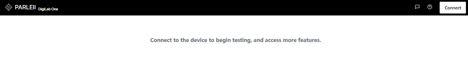
The software is available as a web app:
Connecting to the Device
The software will prompt you to select your device. If it doesn’t, ensure the device is properly connected to your computer and that the drivers are installed. If multiple devices are listed, you can identify yours by unplugging and reconnecting the device.
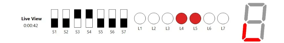
Live Status Update
The software provides real-time status updates for the device, including the status of the lights, 7-segment display, and switches.
The Feature Bar
Located directly below the status window, the feature bar allows you to navigate between different features and tests within the app.
Important Information
- While inside of any of the testing pages the
?icon can be selected to read more info on the test

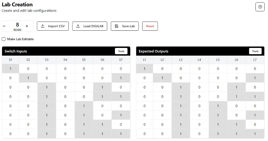
Lab Creation
Important Information
- The
toolsbutton allows you to quickly manipulate a table. - Lost edit passwords are not recoverable.
- Both
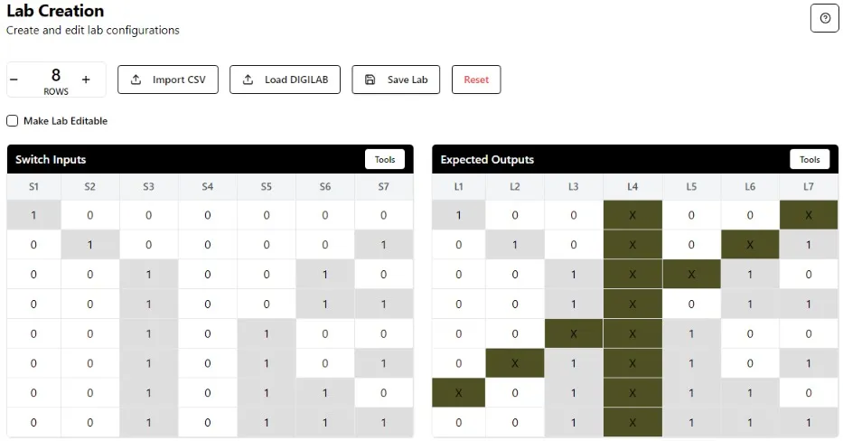
editableandnon-editable.digilabfiles use secure encryption. Non-editable.digilabfilescannotbe converted.Editable.digilabfilescan beconverted tonon-editable.- Expected output supports
don’t-cares, meaning the test will pass regardless of the measured output for that light.
The Lab Creation tab allows users to define input and expected output values. This file can be saved as a .digilab file to be used on the Lab Testing page. To make the .digilab file editable, you must enter a password at the bottom of the page. With or without the password the access is restricted to the unencrypted truth tables, meaning the edit password is only to make it editable.
While creating labs, the expected output can include don’t-cares represented as x's.
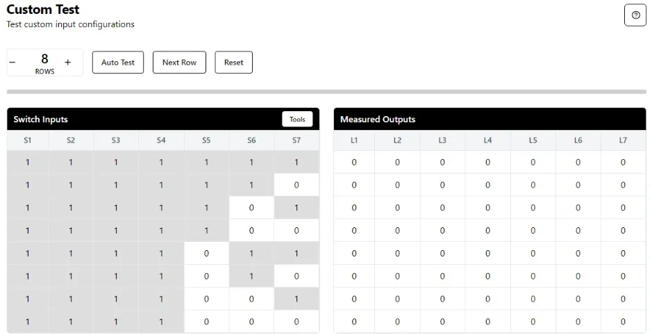
Custom Test
Important Information
- There is
no pass or fail; this feature is only used to observe the states of your circuit. - Failing a row will not stop the test; the user can
pause,step, orresetat any time.
Wiring
- Verify that you’re using the correct
S1throughS7andL1throughL7per your truth table, instructions, or your own specifications. Custom Testdoes not interfere with theDigilab One CLK
After clicking Custom Test, the software allows you to test the device by entering input values from a truth table. The output will be displayed in real time.
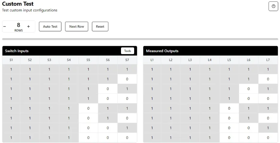
After clicking Auto Test, the output table will populate with responses as the software processes each row of the input table.
Lab Testing
Important Information
- Only
.digilabfiles are accepted. - The expected output for the test is
hiddenfrom the user, it only displayspassorfailfor each state - Failing a row will not stop the test; the user can
pause,step, orresetat any time.
Wiring
- Verify that you’re using the correct
S1throughS7andL1throughL7per your truth table, instructions, or your own specifications. Lab Testingdoes not interfere with theDigilab One CLK
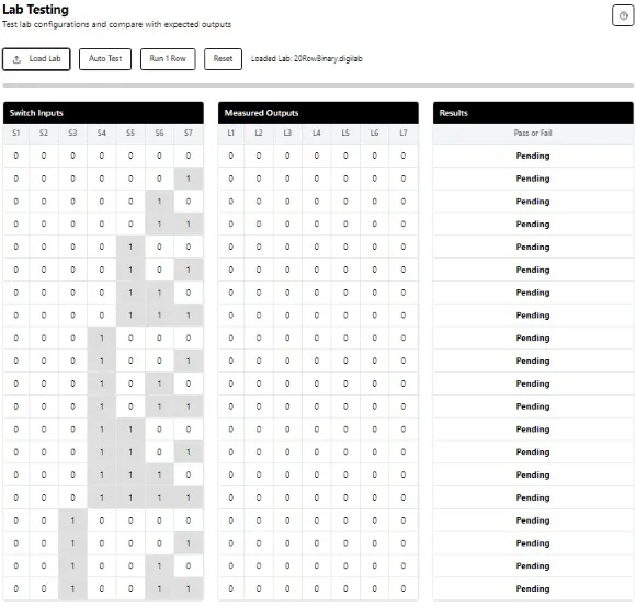
This page allows users to upload a .digilab file, which is an encrypted predefined truth table. Once the lab is successfully loaded, the user can run the test to see if their circuit matches the defined table.
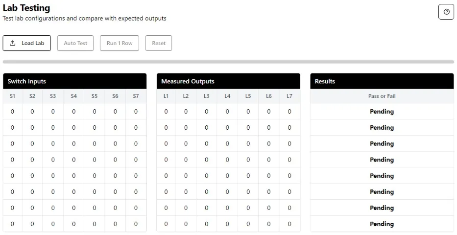
After uploading a .digilab file, the input table will be populated with the relevant information.
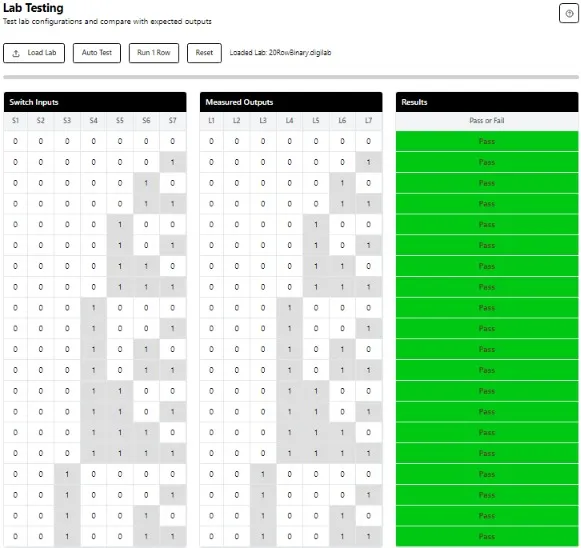
After selecting Auto Test, the tables will populate with the results.
State Machine
Important Information
Word 1andWord 2are required.- Extra states to test are optional.
- Failing the test at any point will stop the test.
Wiring
- The
CLK pinfor the state machine should be connected to theCLK pinof the digilab one when running the tests - The
input pinof the state machine should be connected toS7of the digilab one when running the tests - The software will take control to toggle the clock on and off, and well as toggling
S7to control input, to test your state machine against the defined configuration.
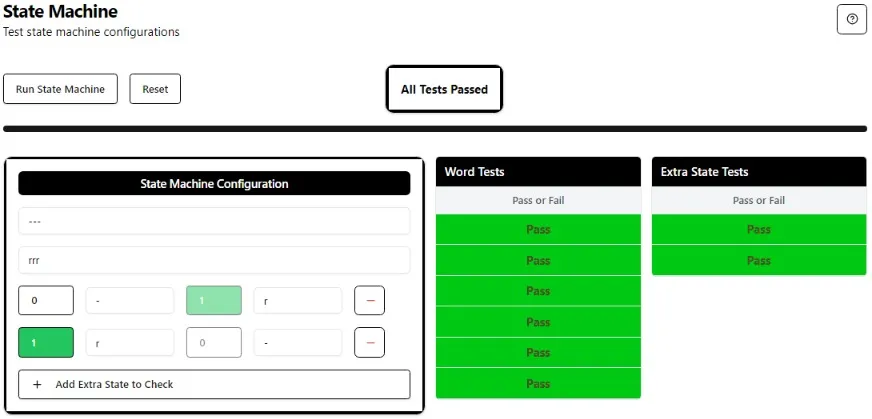
After clicking State Machine, the software allows you to test the state machine against the requirements. You can enter Word 1, Word 2, and additional edge case checks, with the numbers indicating the state in which the first letter can be found.
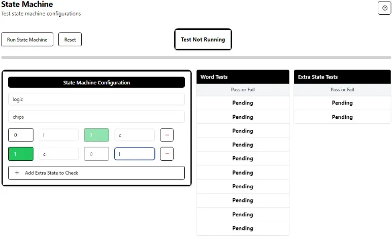
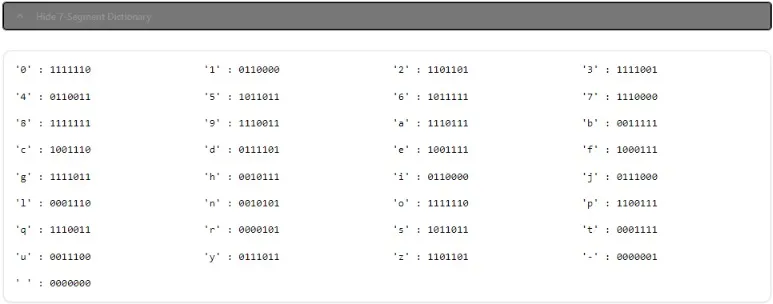
When filling out the State Machine configuration at any time the 7-segment-dictionary can be seen below the table
When auto test is clicked the software will scan through the states with the CLK and S7, until it reaches the first state of Word 1 or fails. Once it finds the first state, it will continue testing each state in sequence to ensure the state machine matches the configuration.